Ultimate guide to parallel inverter operation and phase
Both the voltage and frequency of each inverter must match at every instant. If one inverter''s sine wave is out of step with the others, it can create a
Both the voltage and frequency of each inverter must match at every instant. If one inverter''s sine wave is out of step with the others, it can create a
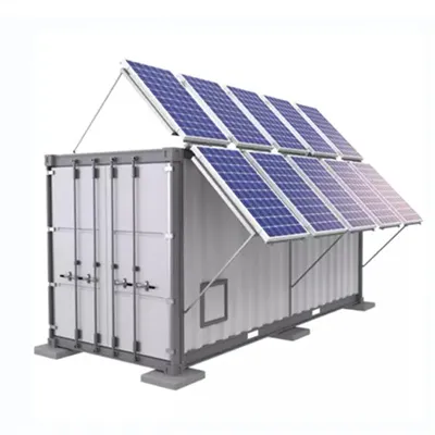
Properly connecting inverters in series can effectively scale your power system''s voltage output while maintaining operational flexibility. Remember to prioritize equipment compatibility and implement
The total voltage you get from one out and back, even with a high temperature difference is pretty small. By putting many of these out and back combinations together, you can get a useful voltage. A single
Is there a way to setup a voltage supply with voltage jitter/noise? I want to experiment with filtering out noise on various voltages etc. but not sure how to configure LTSpice to create a
In this case, the voltage across the current source I depends only on R. With other words: The voltage across a constant current source depends on the external network only.
Each of these 3 phases has an alternating voltage of 230 Volt (or a different voltage, depending on the country). The voltage alternates at a frequency of 50 (or 60) Hz. And because the coils in the
The reason the voltage across the motor dies away slowly is because in the absence of current driven through it, it becomes a generator. That is, the spinning rotor has momentum, and
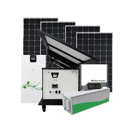
Definition: This calculator determines the total voltage, current, and power output of solar panels connected in series and parallel configurations. Purpose: It helps solar installers and DIY enthusiasts

One might think that to realize a balanced 3-phase inverter could require as many as twelve devices to synthesize the desired output patterns. However, most 3-phase loads are connected in wye or delta,

I saw in schematics they place a resistor in series to the gate and a diode connected to source. What exactly is the purpose of each? How can we cap the gate voltage to say 10V? The
Example: The full-bridge inverter has a switching sequence that produces a square wave voltage across a series RL load. The switching frequency is 60 Hz, Vs=100 V, R=10 Ω, and L=25 mH.
Your title says DC current source but, for whatever reason, your formula is implying a voltage source. So the answer to your title question depends on what source is used.
Series wiring is the standard approach for string inverters, which need a minimum voltage to start operating (typically 150-200V). By connecting 8-20 panels in series, you create a string
Wiring solar panels in series means connecting the positive terminal of one panel to the negative terminal of the next panel, creating a chain that
source. A voltage source inverter employing thyristors as switches, some type of forced commutation is required, while the VSIs made up of using GTOs, power transistors, power MOSFETs or IGBTs, self

Likewise, if the current and voltage are below a certain level, a person can--given enough time--safely absorb an arbitrarily large amount of electrical energy. Further, if voltage is sufficiently low, the
Are there important points to consider in typical or special applications when capacitors operate with applied voltage close to their rated DC voltage? Such as: 15 V on a 16 V-rated
7 One word: Resistance. Recall that Voltage is calculated by multiplying the current by the resistance. You can have a high potential difference (which is what voltage is), and a low current,
PDF includes complete article with source references.
Download solar street light datasheets, pricing guides, and custom specification templates.
15 Galaxy Avenue, Linbro Business Park
Sandton, Johannesburg, 2065
ZA: +27 11 568 4021
EU (Germany): +49 89 4520 8912
Mon-Fri: 8:30 AM – 5:30 PM (SAST / CET)